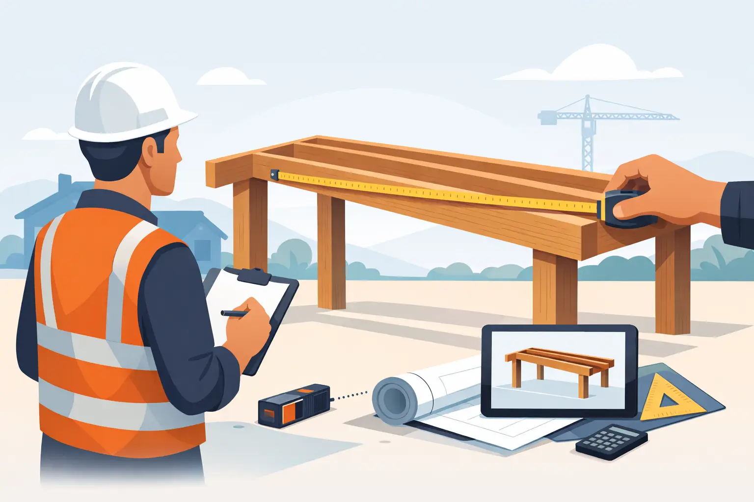
A timber member can look right in place and still be wrong for the job. The issue is usually not the tape measure. It is confusing the distance between walls with the actual structural span, or selecting a member before checking the load it carries. To calculate timber span length properly, start with the supports and work through the load path before you open a span table.
For roof framing, floor joists, lintels and bearers, a correct span measurement is only one part of the decision. Member size, timber species and grade, spacing, tributary load, roof type, wind classification and bearing details can all change what is acceptable. Treat the calculation as a recordable site check, not a rough estimate written on an offcut.
What timber span length actually means
Timber span is the distance a structural member bridges between its supports. In straightforward framing, this is generally the clear distance between the inside faces of the supporting walls, beams, bearers or posts.
For example, a floor joist sitting on two bearers has a span measured from the inside face of one bearer to the inside face of the other. The bearing length at each end is not usually added to the clear span for a basic on-site measurement. A 3.60 m gap between supports is a 3.60 m clear span, even if the joist has 45 mm of bearing at both ends.
Do not confuse span with member length. A joist cut at 3.75 m may have a 3.60 m span once its end bearings are allowed for. Likewise, an overhanging rafter has a span over its supports and a separate cantilever beyond the outside support. They must be checked as different parts of the member.
Clear span, effective span and overall length
These three measurements often appear on the same job:
Clear span is the open distance between support faces. This is the measurement most commonly used when reading residential timber span tables.
Effective span is a structural design term that may be defined differently under a particular engineering method or table. Depending on the system, it can account for support width or centre-to-centre spacing. Use the definition stated in the table or engineering documentation rather than substituting your own.
Overall member length includes bearings, tails, overhangs and any connection allowance. It is essential for ordering and cutting, but it is not automatically the span used to size the timber.
How to calculate timber span length in the field
The process is simple when the framing layout is clear. The discipline comes from checking that each support is real, continuous and capable of carrying the reaction.
1. Identify the member and both supports
Confirm what you are measuring: a floor joist, ceiling joist, rafter, lintel, bearer or beam. Then identify the two points transferring its load down through the structure.
A trimmer may support a header, a bearer may support floor joists, and a loadbearing wall may support roof trusses. Do not take a measurement to a non-loadbearing partition simply because it lines up beneath the member. If the support does not carry the load into an adequate structure below, it is not a valid span support.
2. Measure between the correct support faces
Run the tape along the member's direction of span and measure between the inside faces of the supports. Keep the tape straight and parallel to the member. On an existing building, check whether plaster, packing, a ledger or a steel bracket changes the actual bearing point.
Record the result in millimetres. Australian span tables are commonly read in metres or millimetres, but site records are cleaner when dimensions are consistent. Write 3,650 mm rather than mixing 3.65 m, 365 cm and 12 ft equivalents.
If supports are not parallel, measure the longest clear distance. A joist or rafter does not gain capacity because one end of the opening is shorter.
3. Separate any cantilever or overhang
Where a member extends beyond its support, measure the supported span and the overhang separately. A rafter may run from ridge support to external wall plate, then continue to form an eave. The wall-to-ridge dimension and the eave projection are not interchangeable.
Cantilevers introduce different bending and uplift considerations. Do not assume an allowable simple span table covers them unless the table expressly includes the proposed overhang arrangement.
4. Confirm the load direction and spacing
Span length alone never selects timber. You also need to know what the member supports and how much area feeds into it.
For evenly spaced floor joists, joist spacing determines the width of floor carried by each joist. A joist at 450 mm centres carries less tributary width than the same joist at 600 mm centres, so the permitted span may differ. For rafters, roof pitch, roofing weight, ceiling load and wind conditions may affect the selection. A lintel depends on the opening width plus the wall, roof or floor loads above it.
The load path matters just as much. Check that joists bear correctly onto the bearer, that the bearer has suitable posts or walls beneath it, and that footing or slab support is accounted for. Extending one member's span can create an overload further down the structure.
5. Match the result to the correct span table
Once you have the span, use a current table that applies to the job. Select the timber species or product, stress grade, member orientation, member spacing and load category before comparing the measured span with the table value.
A table may state a maximum span for MGP10 or MGP12 timber at a nominated spacing and service condition. Those values are not interchangeable. A deeper member, a higher grade or closer spacing can increase capacity, but only within the table's stated assumptions.
Use the more conservative interpretation when the measurement sits close to a limit. A 3,620 mm measured span should not be treated as 3,600 mm just because that is the maximum shown in a table. Allow for construction tolerances, timber variability and the exact table rules.
A worked site example
A carpenter is checking floor joists over a subfloor. The joists bear on two parallel bearers. Measuring from the inside face of one bearer to the inside face of the other gives 3,480 mm. Each joist has 45 mm bearing at both ends and the joists are set at 450 mm centres.
The span to assess is 3,480 mm. The approximate cut length may be 3,570 mm before any trimming, based on adding bearing at both ends, but that is not the number used as the clear span. The next step is to identify the joist section and grade, confirm the floor load category and use the relevant span table for 450 mm centres.
Now consider the bearer beneath those joists. It does not span 3,480 mm simply because the joists do. Its span is the distance between its posts or wall supports, while its load is influenced by the joist span on each side. Each member gets its own measurement and its own load check.
Common errors that change the answer
The following mistakes are common because they produce a number quickly, but not a reliable one:
- Measuring to outside faces of supports when the table calls for clear span.
- Using overall rafter length, including eave tail, as the roof span.
- Treating a non-loadbearing wall as structural support.
- Reading a span table for the wrong timber grade, spacing or load condition.
- Ignoring a point load from a beam, girder truss, solar installation or concentrated roof support.
- Rounding a span down to fit a preferred member size.
Existing buildings need extra care. Alterations can hide changes in level, decayed bearings, notched members and previous work that does not match the drawings. A tape measurement does not confirm the condition or adequacy of the support.
When a standard table is not enough
Span tables are useful for conventional, within-scope residential framing. They are not a substitute for project-specific design where loads, geometry or materials fall outside their limits.
Get engineering advice where there are long openings, multiple-storey loads, point loads, unusual roof forms, retaining conditions, steel connections, large cantilevers, major alterations or uncertainty about existing supports. Also check the project documentation and applicable requirements before changing a member size or support layout. A member that works in isolation can still fail the wider load path or approval requirements.
For repetitive calculations, record the clear span, support type, spacing, timber grade, table reference and the selected member together. Builders Calculator can help keep those measurements and calculation notes in one job record, rather than leaving the decision on a paper sketch that disappears after the frame inspection.
A clean span measurement gives you a dependable starting point. Pair it with the correct loading information and a table or design that applies to the actual job, and the next person on site can see not only what was selected, but why.